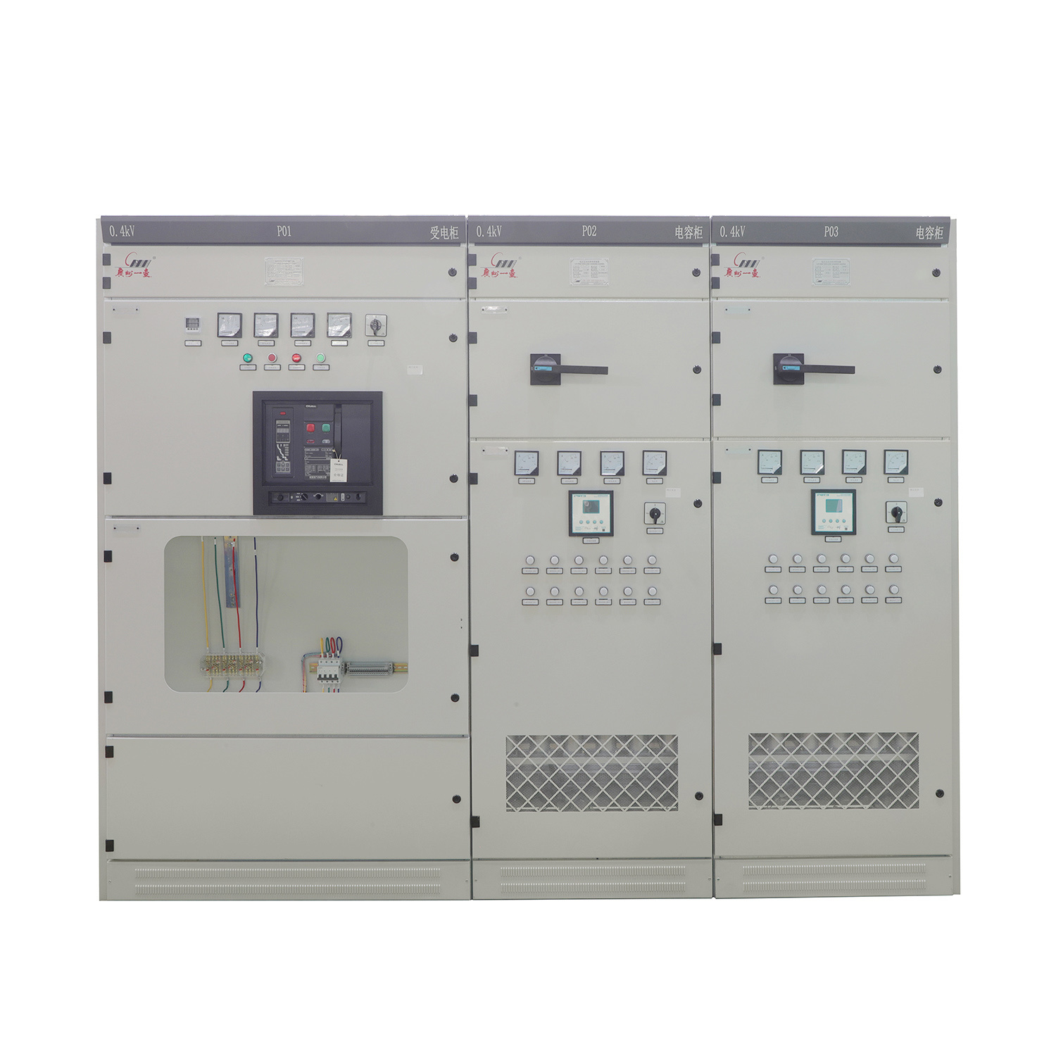
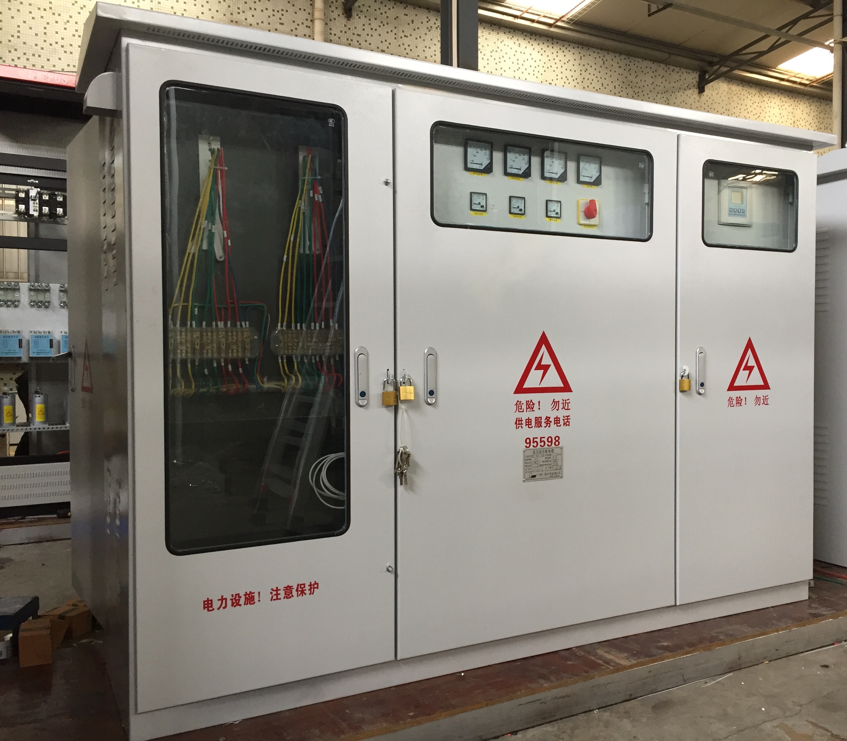
GCS Series Withdrawable AC Low-Voltage Distribution Cabinet
The GCS-type low-voltage withdrawable switchgear is suitable for power conversion, distribution, and control applications in low-voltage distribution systems—including power supply, power distribution, motor control centers, and capacitor compensation—across various settings such as power plants, substations, petrochemical facilities, industrial enterprises, and high-rise buildings.
Category:
Product Center
Low-Voltage Complete Switchgear and Control Equipment
Keywords:
GCS Series Withdrawable AC Low-Voltage Distribution Cabinets
Distribution Cabinets
Low-Voltage Complete Switchgear
and Control Equipment
Service hotline:
GCS Series Withdrawable AC Low-Voltage Distribution Cabinet
Detailed introduction
GCS Series Withdrawable AC Low-Voltage Distribution Cabinet
I. Product Overview
The GCS-type low-voltage withdrawable switchgear is designed for use in low-voltage distribution systems—including power generation plants, substations, petrochemical facilities, industrial and mining enterprises, and high-rise buildings—providing essential functions such as power conversion, distribution, and control for applications like motor control centers, capacitor compensation, and more.
The product complies with GB7251 and IEC61439 standards.
3. Meaning of the Model

3. Operating Environment
1. The ambient air temperature does not exceed 40°C, with a daily average no higher than 35°C; the minimum ambient air temperature is -25°C.
2. The daily average relative humidity does not exceed 95%; the daily average water vapor pressure remains below 2.2 kPa; the monthly average relative humidity is no more than 90%, and the monthly average water vapor pressure does not surpass 1.8 kPa.
3. Altitude not exceeding 2000m;
4. Seismic Intensity: Grade 8; Horizontal Acceleration ≤ 0.4g, Vertical Acceleration ≤ 0.2g;
5. The surrounding air is not noticeably contaminated by dust, smoke, corrosive and/or flammable gases, vapors, or salt spray.
When users have special requirements or the above-mentioned usage conditions cannot be met, they should consult with the manufacturer for a solution.
4. Technical Specifications
| Project | Unit | Standardization |
| Protection Level | Meets IP30 and IP40 ratings as specified by IEC144 and GB4942.2 | |
| Rated Insulation Voltage | V | 660, 1000 |
| Rated Operating Voltage | V | Main circuit: 380–660 V DC, 110–220 V |
| Auxiliary circuit: 220~380 DC, 110~220 | ||
| Controlling the maximum capacity of the electric motor | KW | 300 |
| Mechanical Life | Next time | 50000 |
| Horizontal busbar | A | 630, 800, 1000, 1250, 1600, 2000, 2500, 3150, 4000, 5000, 6300 |
| Vertical busbar | A | 400, 630, 800, 1000, 1250, 1600, 2000 |
| Power-receiving circuit | A | 400, 630, 800, 1000, 1600, 2000, 2500, 3150, 4000 |
5. Product Features
1. The main frame of the device is made from MF steel sections or C-profiles, with a construction that combines both bolted assembly and partial welding. All components of the main frame feature mounting modular holes spaced at E = 20 mm intervals.
2. The device’s functional compartments are strictly separated, with the main sections divided into function unit rooms, busbar rooms, and cable rooms—each serving a relatively independent purpose.
3. The device does not adopt the traditional design of placing the horizontal busbar on top of the cabinet, instead providing cable compartments with outlet channels both at the top and bottom—thus resolving the issue that made it impossible to route cables upward in older products.
4. The dimension series for the equipment cabinet are listed in Table 3:
Table 3: Cabinet Dimensions
| Tall Height | Wide Width | Deep Depth |
| 2200 | 600 | 800 |
| 1000 | ||
| 800 | 600 | |
| 800 | ||
| 1000 | ||
| 1000 | 600 | |
| 800 | ||
| 1000 |


