MNS Series Withdrawable AC Low-Voltage Distribution Cabinet
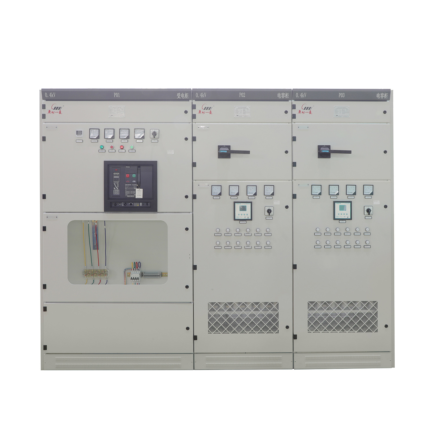
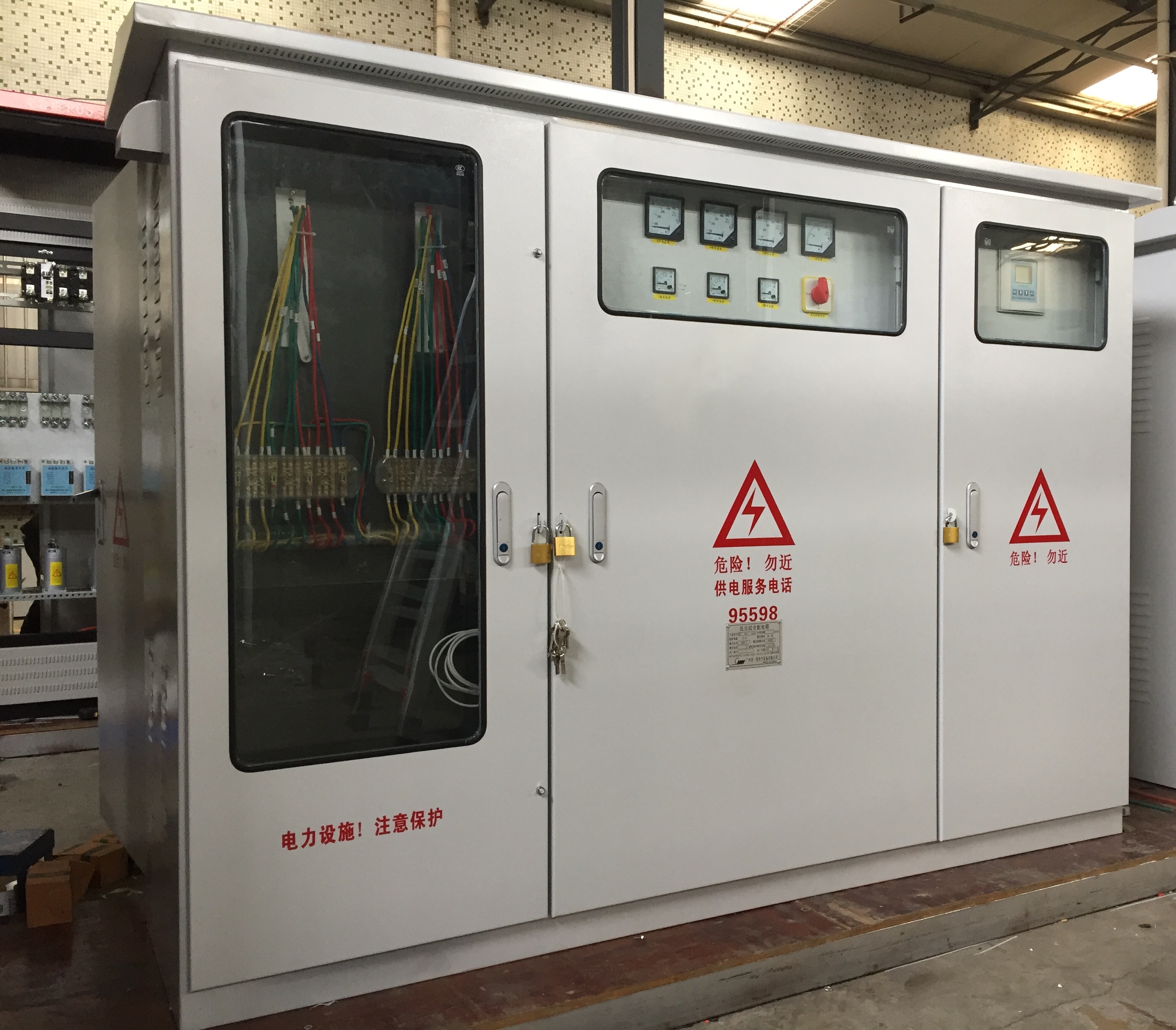
The MNS low-voltage withdrawable switchgear features a state-of-the-art modular assembly structure, allowing for both front- and rear-access operation. It is widely applicable in power plants, substations, airports, hospitals, metro projects, petrochemical facilities, metallurgical steel mills, as well as residential communities and high-rise buildings—serving as equipment for controlling and distributing electrical energy in AC systems operating at 50–60 Hz with rated voltages of 660V or lower. The product complies with GB7251 and IEC61439 standards.
Category:
Product Center
Low-Voltage Complete Switchgear and Control Equipment
Keywords:
MNS series withdrawable AC low-voltage switchgear
distribution cabinets
low-voltage withdrawable switchboards
and low-voltage complete switchgear and control equipment
Service hotline:
MNS Series Withdrawable AC Low-Voltage Distribution Cabinet
Detailed introduction
MNS Series Withdrawable AC Low-Voltage Distribution Cabinet
I. Product Overview
The MNS low-voltage withdrawable switchgear features the most advanced modular assembly structure, allowing for either front-side or rear-side operation. It is widely used in power plants, substations, airports, hospitals, subway projects, petrochemical facilities, metallurgical steel mills, as well as factories, mines, residential communities, and high-rise buildings. This equipment serves to control and distribute electrical energy in AC distribution systems operating at 50–60 Hz with rated voltages of 660V or lower. The product complies with GB7251 and IEC61439 standards.
II. Model Designation Meanings

III. Operating Environment
1. Ambient air temperature: Not higher than +40°C, not lower than -5°C, and with an average temperature no higher than +35°C over any 24-hour period.
2. Relative Humidity: Not exceeding 50% when the ambient temperature reaches up to +40°C. At lower temperatures, higher relative humidity levels are permitted—up to 90% at +20°C, for instance—though it should be noted that occasional moderate condensation may occur due to temperature fluctuations.
3. Saturation Vapor Pressure: The daily average shall not exceed 2.2 × 10⁻³ MPa, and the monthly average shall not surpass 1.8 × 10⁻³ MPa;
4. Altitude: Not exceeding 2000 meters;
5. The seismic intensity does not exceed 8 degrees;
6. Locations free from fire hazards, explosion risks, severe pollution, chemical corrosion, and intense vibrations.
7. This device is suitable for transportation and storage under the following temperature conditions: ranging from -25°C to 55°C, with short-term exposure (no more than 24 hours) up to +70°C. At these extreme temperatures, the device must remain free from any irreversible damage and continue to function properly under normal operating conditions.
If the above-mentioned conditions of use cannot be met, users should consult with the manufacturer to reach a resolution.
4. Technical Specifications
| Project | Unit | Standards |
| Meets the standards | IEC60439, GB7251, JB/T9661 | |
| Protection Level | IP30, IP40, IP54 (Note: Please consult with the manufacturer when ordering the IP54 protection rating.) | |
| Main circuit rated insulation voltage | V | AC660(1000) |
| Main circuit rated operating voltage | V | AC380(1000) |
| Rated frequency | HZ | 50 or 60 |
| Busbar Rated Operating Current | ||
| Horizontal Busbar (Main Busbar) | A | 1000 to 5000 |
| Vertical Busbar (Branch Busbar) | A | 1000–1600 |
| Rated Short-Time Withstand Current (1S) | ||
| Horizontal Busbar (Main Busbar) | kA | 50, 65, 80, 100 |
| Vertical Busbar (Branch Busbar) | kA | 50, 65, 80, 90 |
| Rated Peak Withstand Current | ||
| Horizontal Busbar (Main Busbar) | kA | 105, 143, 176, 220 |
| Vertical Busbar (Branch Busbar) | kA | 105, 143, 176, 198 |
| Note: When the protection rating is IP55, the rated operating current of the main busbar ≤ 2500A. | ||
V. Product Features
1. The MNS-type low-voltage switchgear features a modular frame structure, with the basic skeleton assembled from C-channel steel sections. All structural components of the cabinet frame undergo galvanization and are securely connected into the basic framework using self-tapping locking screws or 8.8-grade hex bolts. These components are then complemented by doors, partitions, mounting brackets, busbar functional units, and other parts tailored to specific design variations, ultimately forming a complete switchgear. Moreover, the internal dimensions of the switchgear, as well as the sizes of its components and compartments, all follow a standardized modular system (E = 25 mm) for flexible customization.
2. Each cabinet of the MNS-type modular low-voltage switchgear is divided into three compartments: the horizontal busbar chamber (located at the rear of the cabinet), the drawer compartment (situated at the front), and the cable chamber (positioned at the bottom or on the right side of the front). The compartments are separated from one another by steel plates or high-strength, flame-retardant plastic functional panels. Additionally, metal plates with ventilation holes are installed between the upper and lower drawer levels, effectively preventing arc flash incidents caused by faulty switching components, as well as short-circuit accidents between the busbars and other circuits.
3. The structural design of MNS-type low-voltage switchgear can accommodate various incoming and outgoing cable configurations: top-in-top-out, top-in-bottom-out, bottom-in-top-out, and bottom-in-bottom-out.
4. Compact Design: Accommodate more functional units within a smaller space;
5. The structural components feature strong versatility and flexible assembly, using E = 25mm as the module. The structure and pull-out units can be combined freely to meet the requirements of system design.
6. The busbar is protected by a high-strength, flame-retardant plastic functional panel with high dielectric strength, featuring fault arc resistance to ensure safe and reliable operation and maintenance.
7. The mechanical interlocking mechanisms for drawers of various sizes comply with standard regulations and feature three distinct positions—connected, tested, and separated—for safety and reliability.
8. Adopting a standard modular design: It can be configured into various standard units such as protection, operation, switching, control, regulation, measurement, and indication—allowing flexible assembly according to specific requirements.
9. Utilizing high-strength, flame-retardant engineering plastic significantly enhances protective safety performance;
10. Highly versatile and standardized, making assembly convenient. Backed by reliable quality assurance;
11. The cabinet can be equipped with appropriate protection levels according to different environmental requirements;
12. Ensuring the continuity and reliability of equipment protection.
Previous page


