
PRODUCTS CENTER

Republic of Vanuatu Modular Transformer (American-style Pad-Mounted Transformer)
Category:
Product Description
Modular Transformer (Modular Substation, American-Style Pad-Mounted Transformer)
I. Product Overview
The ZGS modular transformer is a domestically produced American-style packaged substation. As a critical power supply unit in cable-based distribution networks, this product integrates high-voltage control, protection, power transformation, and distribution equipment into a comprehensive, pre-assembled modular system. It is widely used in both urban and rural distribution networks.
This product features high-voltage load switches and high-voltage fuses immersed in transformer oil, available in two structural designs: either integrated with the transformer tank or housed in a separate enclosure. The oil tank adopts a fully sealed design and is equipped with components such as an oil thermometer, oil level gauge, pressure gauge, pressure relief valve, and drain valve to monitor the transformer's operational status. The product lineup includes ring network, terminal, and dual-power supply configurations. Additionally, depending on the complexity of low-voltage feeder requirements, our company’s modular substation products are categorized into three structural types—standard, enhanced, and comprehensive—to provide users and design engineers with greater flexibility and cost-effectiveness during equipment selection.
II. Operating Environmental Conditions
- Altitude: Not exceeding 2000 meters;
- Ambient temperature : Maximum temperature +40°C;
Minimum temperature: -30°C;
Maximum daily average temperature: +30°C,
Highest annual average temperature: +20°C; - Relative humidity : The daily average does not exceed 95%; the monthly average does not surpass 90%.
- Ground slope : No more than 3 degrees;
- Earthquake intensity : Seismic horizontal acceleration not exceeding 0.4 m/s²
The vertical seismic acceleration does not exceed 0.2 m/s². - Outdoor wind speed : Not exceeding 35 m/s;
- Installation Environment : The surrounding air is free from significant contamination by corrosive or flammable gases, and the installation site experiences no severe vibrations.
If ordering this product exceeds the conditions specified above, please consult with our company's technical specialists.
▬▬▬ Negotiable supplier products for use in specialized environments
3. Meaning of the Model
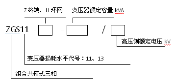
4. Main Technical Parameters
1. Loss Level
Table 1: Performance Parameters of 10kV, 11 Series 30–2500 kVA Double-Winding Oil-Immersed Transformers with No-Load Voltage Regulation
| Rated Capacity | Voltage Combination Kv | Connection Group Designation | No-load loss | Load Loss | No-load current | Short-circuit impedance | |
| High pressure | Low pressure | ||||||
| 30 | 6 6.3 10 10.5 11 |
0.4 0.69 |
Yyn0 Dyn11 Yzn11 |
100 | 630 / 600 | 1.5 | 4 |
| 50 | 130 | 910 / 870 | 1.3 | ||||
| 80 | 180 | 1480/1430 | 1.2 | ||||
| 100 | 200 | 1780/1700 | 1.1 | ||||
| 125 | 240 | 2130/2040 | 1.1 | ||||
| 160 | 280 | 2590/2480 | 1.0 | ||||
| 200 | 340 | 3070/2940 | 1.0 | ||||
| 250 | 400 | 3600 divided by 3450 | 0.9 | ||||
| 315 | 480 | 4310/4130 | 0.9 | ||||
| 400 | 570 | 5090/4870 | 0.8 | ||||
| 500 | 680 | 6090/5780 | 0.8 | ||||
| 630 | 810 | 7010 | 0.6 | 4.5 | |||
| 800 | 980 | 8480 | 0.6 | ||||
| 1000 | 1150 | 11450 | 0.6 | ||||
| 1250 | 1360 | 13360 | 0.5 | ||||
| 1600 | 1640 | 16140 | 0.5 | ||||
| 2000 | 1940 | 20240 | 0.4 | 5 | |||
| 2500 | 2290 | 23490 | 0.4 | ||||
Table 2: Performance Parameters of 10kV, 13 Series 30–2500 kVA Double-Winding Oil-Immersed Transformers with No-Load Voltage Regulation
| Rated Capacity | Voltage Combination Kv | Connection Group Designation | No-load loss | Load Loss | No-load current | Short-circuit impedance | |
| High pressure | Low pressure | ||||||
| 30 | 6 6.3 10 10.5 11 |
0.4 0.69 |
Yyn0 Dyn11 Yzn11 |
80 | 630 / 600 | 1.5 | 4 |
| 50 | 100 | 910 / 870 | 1.3 | ||||
| 80 | 130 | 1310/1250 | 1.2 | ||||
| 100 | 150 | 1580/1500 | 1.1 | ||||
| 125 | 170 | 1890/1800 | 1.1 | ||||
| 160 | 200 | 2310/2200 | 1.0 | ||||
| 200 | 240 | 2730/2600 | 1.0 | ||||
| 250 | 290 | 3200 / 3050 | 0.9 | ||||
| 315 | 340 | 3830/3650 | 0.9 | ||||
| 400 | 410 | 4520/4300 | 0.8 | ||||
| 500 | 480 | 5410/5150 | 0.8 | ||||
| 630 | 570 | 6200 | 0.6 | 4.5 | |||
| 800 | 700 | 7500 | 0.6 | ||||
| 1000 | 830 | 10300 | 0.6 | ||||
| 1250 | 970 | 12000 | 0.5 | ||||
| 1600 | 1170 | 14500 | 0.5 | ||||
| 2000 | 1550 | 18300 | 0.4 | 5 | |||
| 2500 | 1830 | 21200 | 0.4 | ||||
Table 4: Performance Parameters of 10kV, 20 Series 30–2500 kVA Double-Winding Oil-Immersed Transformers with No-Load Voltage Regulation
| Rated Capacity | Voltage Combination Kv | Connection Group Designation | No-load loss | Load Loss | No-load current | Short-circuit impedance | |
| High pressure | Low pressure | ||||||
| 30 | 6 6.3 10 10.5 11 |
0.4 0.69 |
Yyn0 Dyn11 Yzn11 |
70 | 505/480 | 1.8 | 4 |
| 50 | 90 | 730/695 | 1.6 | ||||
| 63 | 100 | 870/830 | 1.5 | ||||
| 80 | 115 | 1050/1000 | 1.4 | ||||
| 100 | 135 | 1265/1200 | 1.3 | ||||
| 125 | 150 | 1510/1440 | 1.2 | ||||
| 160 | 180 | 1850/1760 | 1.1 | ||||
| 200 | 215 | 2185/2080 | 1 | ||||
| 250 | 260 | 2560/2440 | 0.9 | ||||
| 315 | 305 | 3065/2920 | 0.8 | ||||
| 400 | 370 | 3615/3440 | 0.7 | ||||
| 500 | 430 | 4330/4120 | 0.7 | ||||
| 630 | 510 | 4960 | 0.6 | 4.5 | |||
| 800 | 630 | 6000 | 0.6 | ||||
| 1000 | 745 | 8240 | 0.5 | ||||
| 1250 | 870 | 9600 | 0.4 | ||||
| 1600 | 1050 | 11600 | 0.4 | ||||
| 2000 | 1225 | 14640 | 0.4 | 5 | |||
| 2500 | 1440 | 14840 | 0.4 | ||||
Table 5: Performance Parameters of 10kV, 22 Series 30–2500 kVA Double-Winding Oil-Immersed Transformers with No-Load Voltage Regulation
| Rated Capacity | Voltage Combination Kv | Connection Group Designation | No-load loss | Load Loss | No-load current | Short-circuit impedance | |
| High pressure | Low pressure | ||||||
| 30 | 6 6.3 10 10.5 11 |
0.4 0.69 |
Yyn0 Dyn11 Yzn11 |
65 | 455/430 | 1.8 | 4 |
| 50 | 80 | 655/625 | 1.6 | ||||
| 63 | 90 | 785/745 | 1.5 | ||||
| 80 | 105 | 945/900 | 1.4 | ||||
| 100 | 120 | 1140/1080 | 1.3 | ||||
| 125 | 135 | 1360/1295 | 1.2 | ||||
| 160 | 160 | 1665/1585 | 1.1 | ||||
| 200 | 190 | 1970/1870 | 1 | ||||
| 250 | 230 | 2300/2195 | 0.9 | ||||
| 315 | 270 | 2760 / 2630 | 0.8 | ||||
| 400 | 330 | 3250/3095 | 0.7 | ||||
| 500 | 385 | 3900 divided by 3710 | 0.7 | ||||
| 630 | 460 | 4460 | 0.6 | 4.5 | |||
| 800 | 560 | 5400 | 0.6 | ||||
| 1000 | 665 | 7415 | 0.5 | ||||
| 1250 | 780 | 8640 | 0.4 | ||||
| 1600 | 940 | 10440 | 0.4 | ||||
| 2000 | 1085 | 13180 | 0.4 | 5 | |||
| 2500 | 1280 | 13360 | 0.4 | ||||
Note: For transformers with a rated capacity of 500 kVA or less, the load loss and total loss values listed above the slash in the table apply to the Dyn11 connection group, while those below the slash are applicable to the Yyn0 connection group. Additionally, the measured values for no-load loss and load loss are allowed to deviate by up to +15%; the measured total loss can vary by up to +10%, and the measured short-circuit impedance is permitted to differ by ±10%. Finally, the measured no-load current deviation is allowed to be within +30%.
2. Insulation Level
Table 6
| Rated Voltage (RMS) | Maximum device voltage (RMS) | Rated Lightning Impulse Withstand Voltage (Peak) | Rated short-time power frequency withstand voltage (1 min) (RMS) | |
| Full-wave | Clipped wave | |||
| ≤1 | 2 | ▬ | ▬ | 5 |
| 6 | 7.2 | 60 | 65 | 25 |
| 10 | 12 | 75 | 85 | 35 |
| 20 | 24 | 125 | 140 | 55 |
| 35 | 40.5 | 200 | 220 | 85 |
5. Product Structure
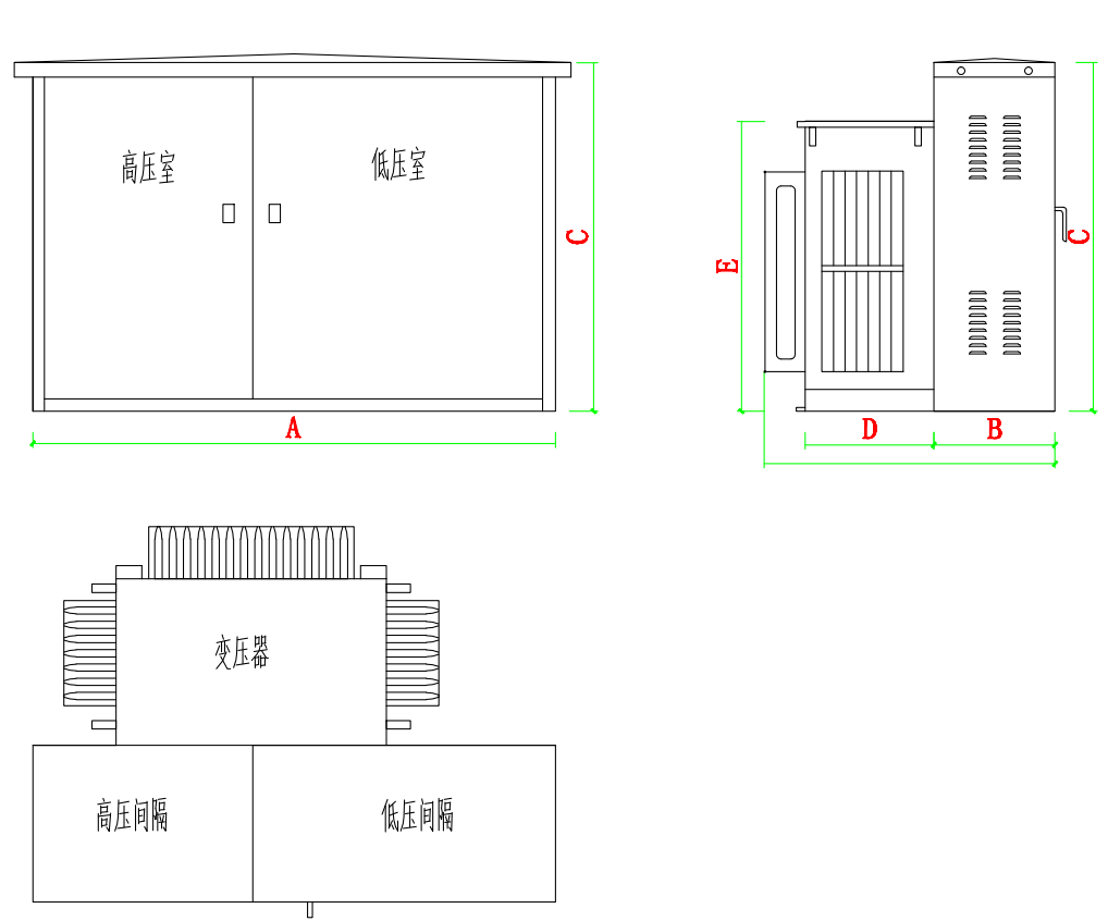
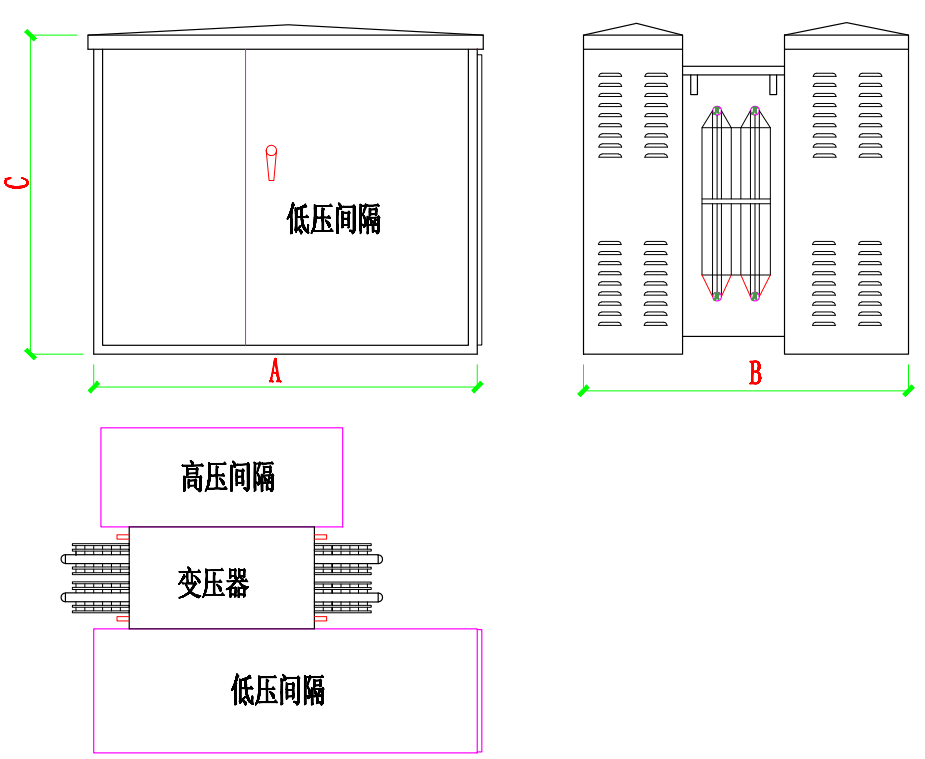
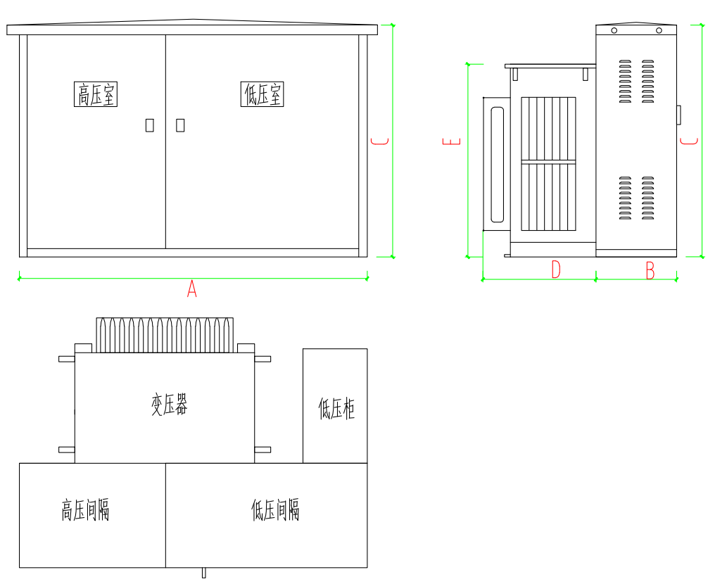
Our company has developed a variety of integrated, compact American-style substations featuring "U," "H," and L-shaped designs, as well as high-voltage models with built-in metering systems—tailored to meet the usage habits and requirements of China's power distribution equipment. In terms of power distribution, the low-voltage outgoing lines can be equipped with main switches, total and individual circuit metering, multiple branch circuit outputs, phase-loss trip mechanisms, automatic reactive power compensation, real-time electricity monitoring, and other advanced automation features. These substations are equally suitable for a wide range of applications as European-style substations, fully replacing traditional brick-and-mortar transformer stations. They also offer exceptional flexibility in installation, ensuring reliable and safe power supply while maintaining high mobility.
It also has the following unique advantages:
1. Low-noise and environmentally friendly
2. No Leakage
3. Strong short-circuit resistance
4. High dielectric strength
5. Excellent weather resistance
Pin-shaped
Eye-shaped
L-shaped
High-Voltage Infeed Solution
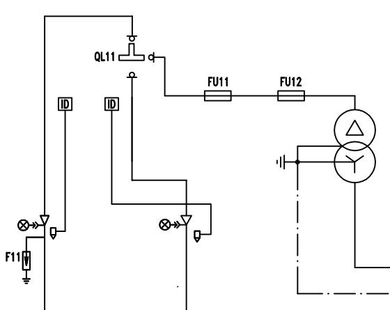
| Name | Terminal-based power distribution | Ring Network Power Distribution |
| System Solution | 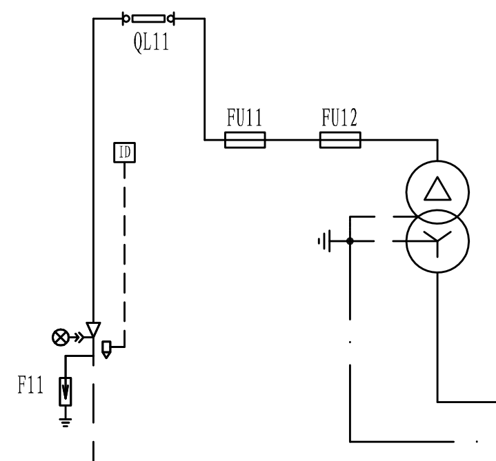 |
 |

Company Address:
No. 9 Qianfeng North Road, Shiji Town, Panyu District, Guangzhou City

Follow us
Copyright © Guangzhou Yibian Electrical Equipment Co., Ltd. Urban sub station Power by 300.cn SEO